Step 8: LIDAR PCB
New parts used in this step (see the Parts List for details):
- LIDAR PCB
- Four 4-40 standoffs
- Four 4-40 1/4 screws (E)
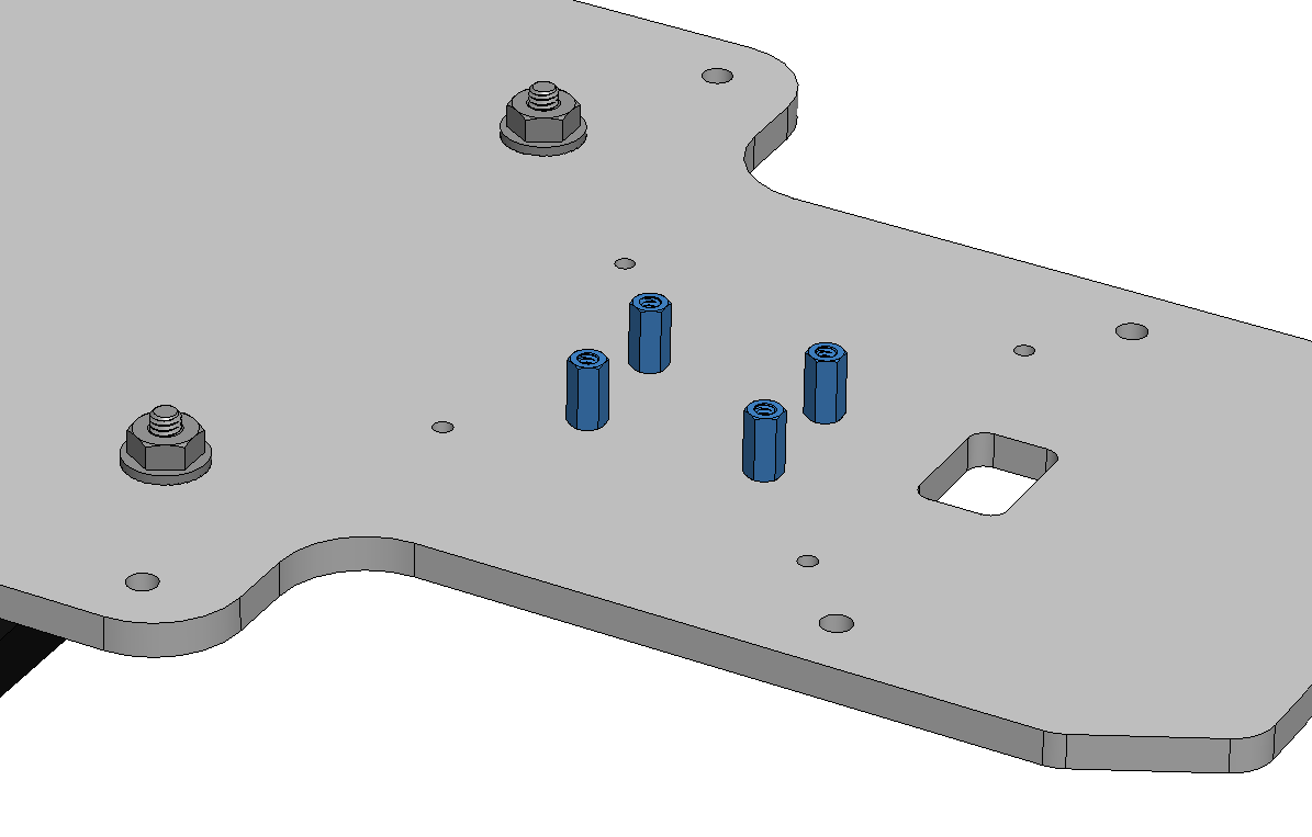
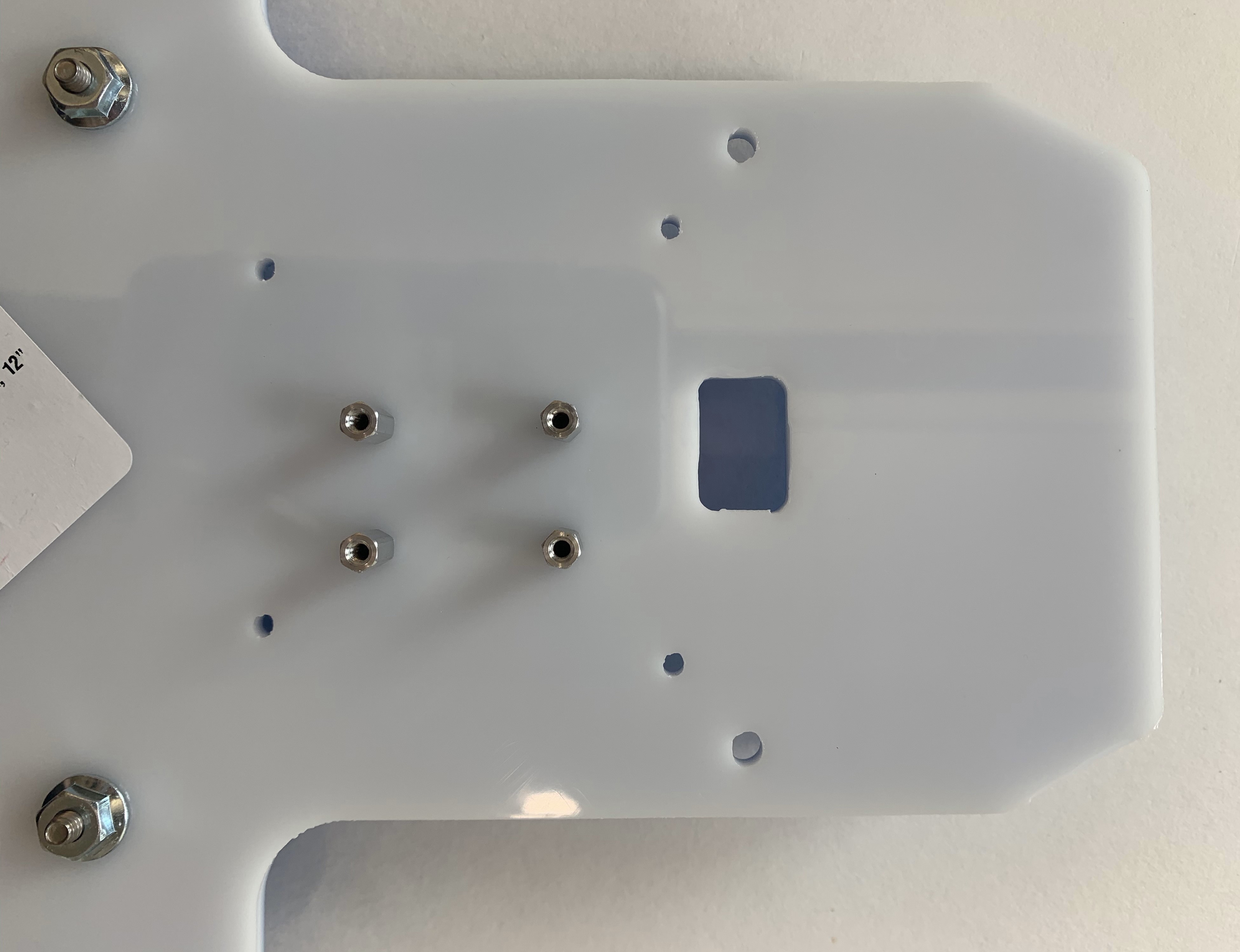
8.1 Attach Standoffs
Screw tightness: very gentle
Gently screw four 4-40 MF standoffs into the four holes shown on the uncolored side of the top plate using a 3/16 hex screwdriver. These holes are toward the front of the plate.
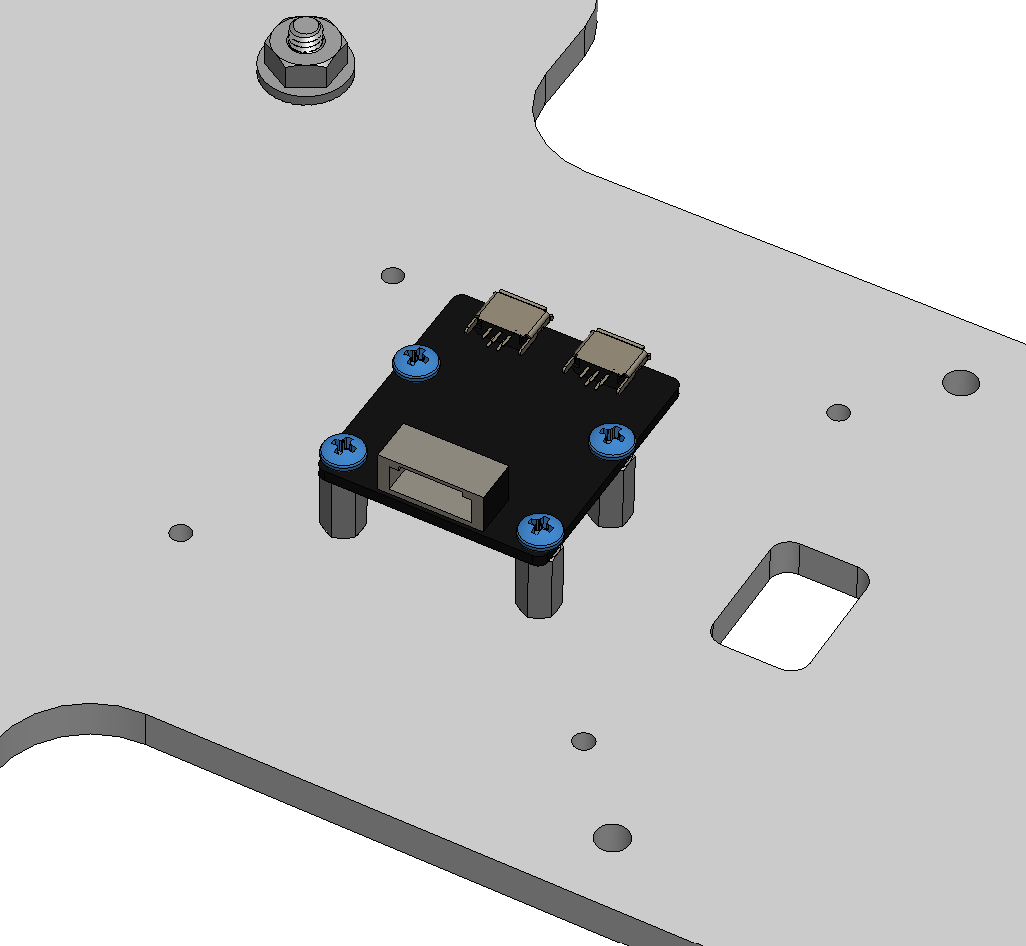
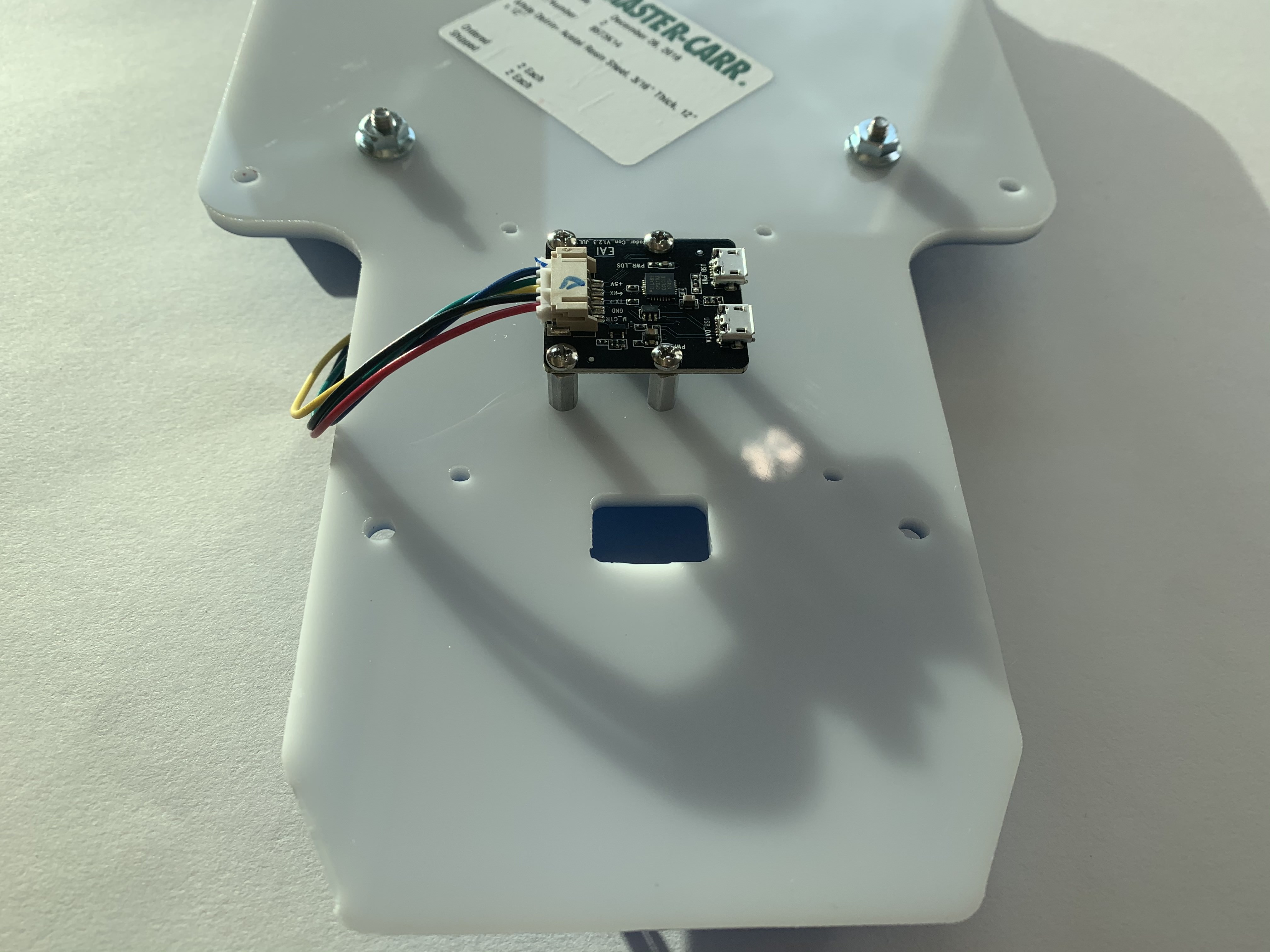
8.2 Attach LIDAR PCB
Warning: discharge any static before touching the LIDAR PCB
Screw tightness: gentle
Carefully align the four screw holes of the LIDAR PCB with the 4-40 MF standoffs attached in step 8.1. Make sure that the two micro USB ports of the LIDAR PCB point upward as shown in the picture below. Secure the the LIDAR PCB to the standoffs using four 4-40 1/4 screws (E). Tighten the screws with a small Philips screwdriver using a crisscross pattern with multiple stages.